Groundschool
Principles of Flight - Table of contents
The forces that act upon an aeroplane
The modern light aircraft

|
The Four Forces that act upon an Aeroplane in Flight
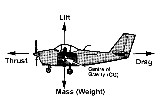
Mass
The mass of the aircraft acting straight down towards the earth.
Thrust
Thrust, supplied by the engine turning the propellor.
Lift
Lift is generated by the airflow around the wings.
Drag
Drag is the resistance to the movement of the aircraft through the air.
Weight is balanced by the lift
Drag is balanced by the thrust
NB: in light aircraft lift will be approximately 10 times the drag
This is known as the lift drag ratio
Weight
Centre of gravity - weight may be considered to act as a single force through the centre of gravity
Weight is the most reliable force always acting in the same direction, and gradually reducing as fuel is used
Wing loading = weight of aeroplane / wing area
The C of G moves as weight is redistributed
Aerofoil - lift
Static Pressure: Ambient Pressure At The Same Level As The Aircraft
Total Pressure: Pressure in air which has been brought to rest from the free stream
Dynamic Pressure: Difference between total pressure and static pressure
Venturi - Bernoulli high flow low static pressure

Total pressure = static pressure + dynamic pressure
Dynamic pressure = ½ r v2 (r:Air density / V:speed)
Low static pressure on top of an aerofoil section
Aerofoil definitions
Leading Edge - Trailing Edge - Chord Line - Thickness

Camber - Mean Camber Line

Relative airflow - the airflow and its direction relative to the aircraft but undisturbed by the aircraft

Angle of attack - angle between chord line and direction of relative airflow
Angle of incidence - longitudinal axis of aircraft and the chord line
Dihedral - wings at an angle to the lateral axis
Sweepback - angle between LE and lateral axis

Centre of pressure - point where resultant lift acts
Centre of pressure changes with angle of attack
Moving forward with increase in AoA

Centre of pressure changes with change of wing shape

Lift = Clift ½ r v2 s
Clift represents shape and angle
Rho (r) is air density
V is velocity (true air speed)
S is area

Lift from symmetrical aerofoil - zero lift @ zero AoA
Drag
Total drag is total resistance to motion
Made up from
Parasite drag
Induced drag
Parasite drag- skin friction, form drag, interference

Ways of reducing parasite drag:
|
Induced drag - lift
High static pressure under an aerofoil, leaks via the wing tips to the low static pressure ontop
This causes a spanwise flow outboard underneath and inboard ontop of the aerofoil
Spanwise flow causes induced lift

there is an overall downwash of air behind the trailing edge

Which leads to the lift force being inclined into the drag direction
Aspect ratio = span / mean chord
High aspect ratio give less induced drag for a given lift
Low aspect ratio give less profile drag for a given lift

Other ways of reducing induced drag included
|
Total drag versus airspeed

Drag = Cdrag ½ rv2 s
Cdrag represents shape and angle
Rho (r) is air density
V is velocity (true air speed)
S is area
Lift / Drag ratio
The best lift drag ratio is the most efficient Speed (and AoA) for Maximum Range ie Minimum Drag Vmd

Lowering gear (or flaps) changes the drag characteristics

Thrust from the propeller
Propeller terminology
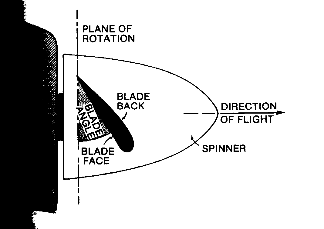
The propeller blade angle is made progressively smaller from hub to tip to provide efficient angles of attack along its full length
NB: the propeller has "washout"
Propeller torque - is the resistance to motion in the plane of rotation
Fixed pitch propeller: angle of attack varies with forward speed and rpm
Variable pitch propeller: a constant speed unit retains an efficient angle of attack over a wide forward speed range by altering the blade angle automatically
Take off effects of propeller:
Slipstream, causes asymmetric flow over fin, resulting in yaw
Overcome with offset fin
Propeller torque reaction: with a clockwise rotating propeller (seen from behind), the aircraft will tend to want to roll left
Gyroscopic effect in tailwheel: pitch forward on take off run, yaw left
Stability
For an aircraft to be in equilibrium the opposing forces must be and opposite, leaving no resultant force
Under normal circumstances c of g and c of p are not coincident:
Lift and weight produce a pitching couple
Under normal circumstances thrust line and drag line are not coincident:
Thrust and drag produce a pitching couple
The tailplane produces a stabilising force to counteract these pitching couples
Axes of motion
Angular motion:
Rolling about the longitudinal axis
Pitching about the lateral axis
Yawing about the normal axis
Stability:
Longitudinal stability is stability about the lateral axis
Lateral stability is stability about the longitudinal axis
Directional stability is stability about the normal axis
Stability is the natural ability of the aeroplane to return to its original condition after being disturbed without any action being taken by the pilot
A Neutrally stable aircraft will, when disturbed remain in the new position, neither returning to its original attitude nor increasing its movement in the direction of disturbance
Unstable:
An unstable aircraft will continue to move away from original attitude after a disturbance
Stable:
A stable aircraft will return to its original attitude after a disturbance
Elevator: primary pitching control
To retain satisfactory handling characteristics and elevator effectiveness the position of the c of g must be kept within a limited range
The aft limit of the c of g is determined by the requirement for longitudinal stability
Aileron: primary rolling control
Adverse aileron yaw due to aileron drag:
Down going aileron causes drag (more lift), and hence yaw out of the turn
Overcome with:
|
Rudder: primary yaw control
Note secondary effects
Roll causes yaw
Yaw causes roll
Note further effects of controls:
Spiral descent
Control effectiveness
Slipstream increases the effectiveness of rudder and tailplane
Desirable qualities:
Elevator and rudder authority at slow speed
Trim provides aerodynamic balance
Horn balance
Inset hinge line
Balance tab
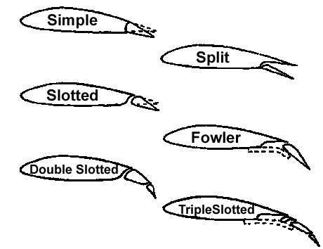
Flaps
Trailing edge flaps
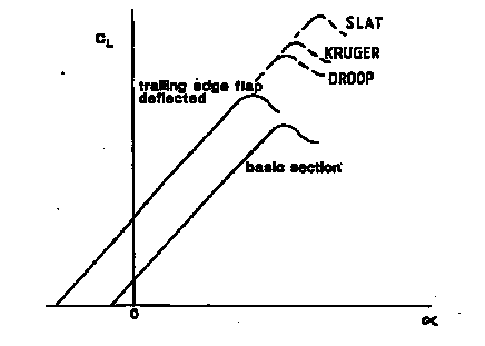
Leading edge devices

Straight and level
In steady straight and level flight the aeroplane is in equilibrium
The tailplane provides the final pitching moment for any pitching couples
ATTITUDE: IAS varies inversely with AoA
WEIGHT: For the same power a lighter aircraft has a lower AoA
Climbing
Forces in the climb: Weight force acts vertically, but has a component the acts in the direction opposing flight
Thrust is greater than drag; lift is less than weight
Descending
In a glide a component of weight balances drag
Estimation of gliding distance in still air
With a Lift/Drag ratio of 12:1 horizontally 12 times further in still air than the height it descends
Turning
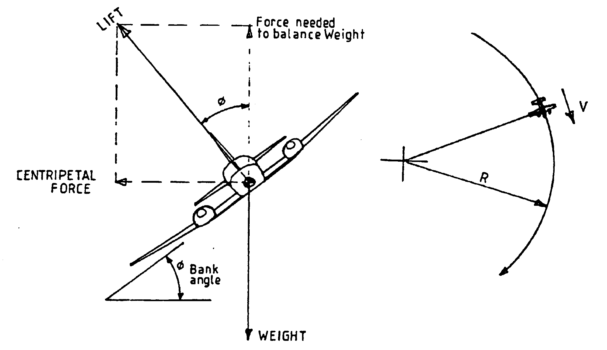
During a properly executed horizontal turn, the inward force is provided by banking the aircraft to vector the lift
An increase in lift is obtained by increasing the AoA by pulling back on the control column
Load factor = lift / weight
Load factor will increase, so will stalling speed
Ex. At 60 degree banked load factor increases by 2, stall speed Vs increases by Öload factor = Ö2 = 1.4
Stalling
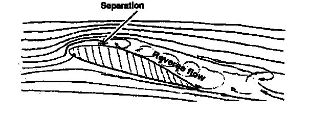
RECOGNITION OF STALL
|
NB Stalling is associated with a particular AoA
Usually this is 15-16 degrees in modern training aircraft
Stalling Speed varies with Ölift
Stalling speed therefore increases with increase in weight
Washout provides desirable stalling characteristics
Spinning
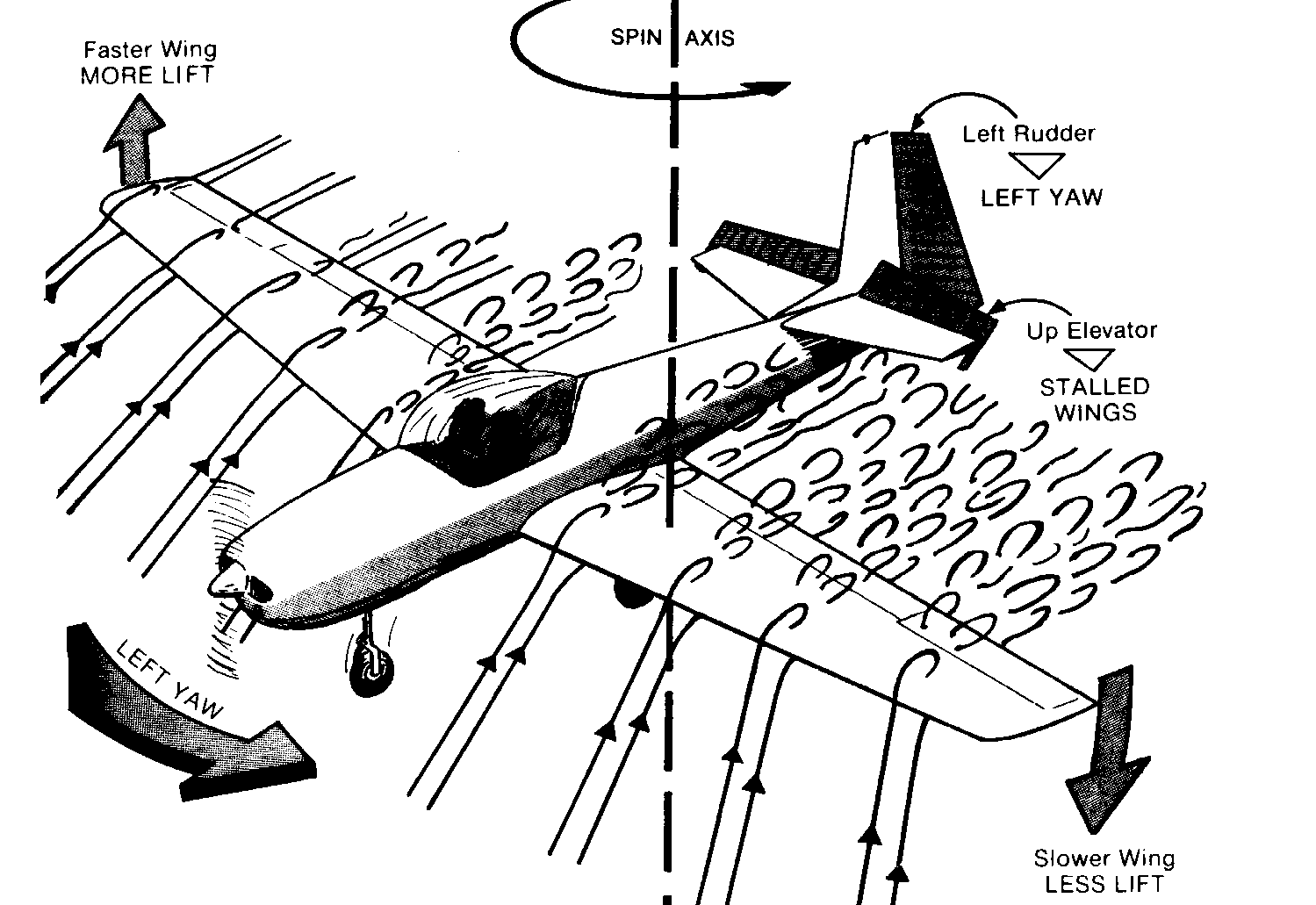
If an aircraft drops a wings at or near the stall the downgoing wing AoA increases, the upgoing wing AoA decreases.
This can cause a continuing rolling, yawing condition known as autorotation
Recovery opposite rudder to stop yaw and roll, then forward elevator to pitch the nose down, followed by a pull out of ensuing dive (if you have enough height!)
Other Groundschool subjects
Introduction to the PPL ~ Air Law ~ Propellers ~ Navigation
Home ~ PPL ~ NPPL ~ IMC ~ Night ~ Aerobatics ~ Multi ~ CPL ~ IR ~ FIC